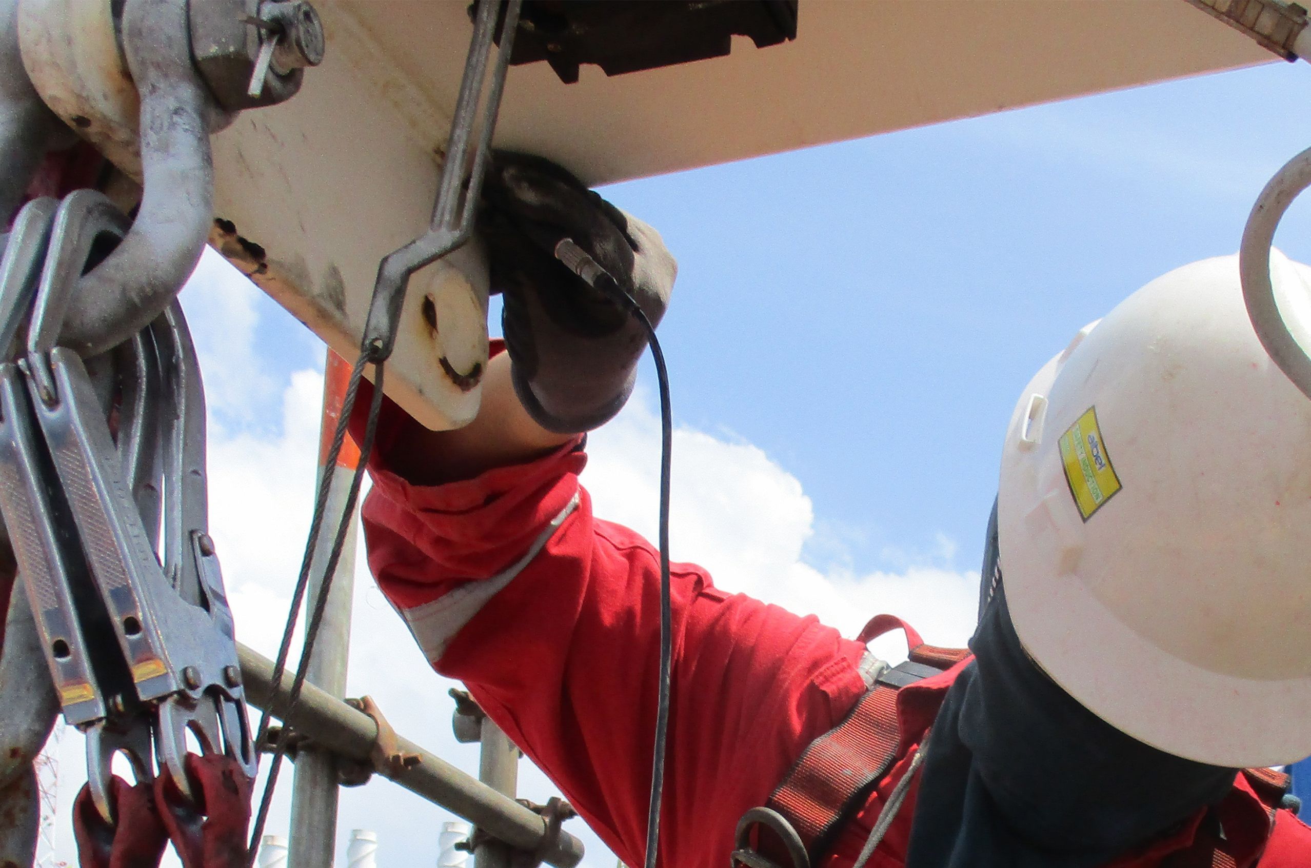
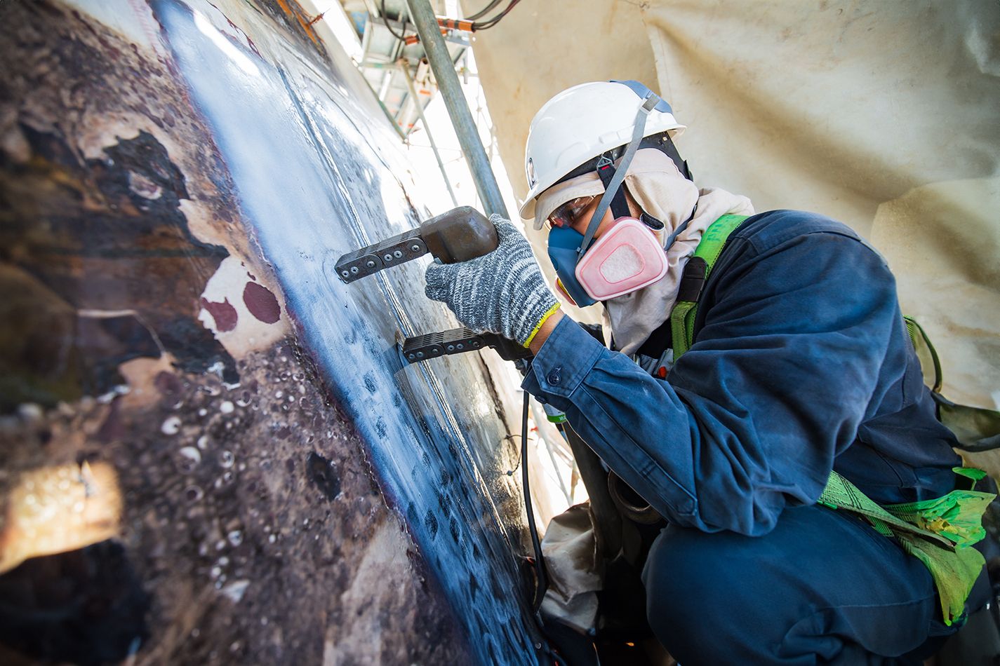
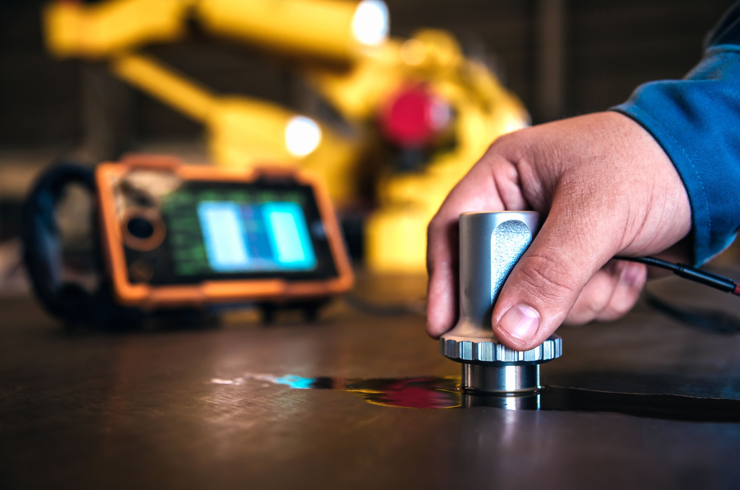
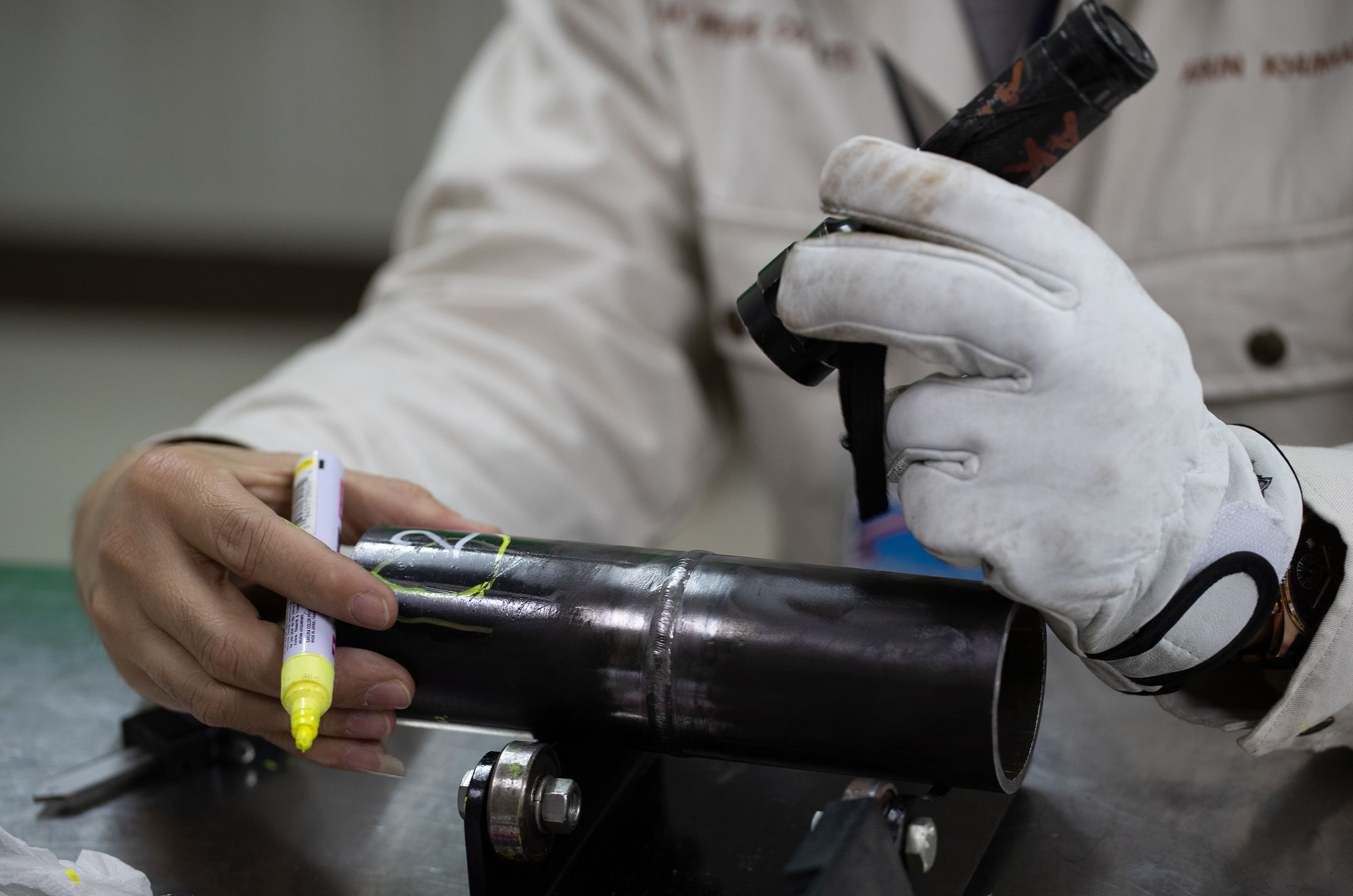
ET Techniques
Eddy Current Testing

When an alternating current coil induces an electromagnetic field into a conductive test piece, a small current is created around the magnetic flux field, much like a magnetic field is generated around an electric current. The flow pattern of this secondary current, called an "eddy" current, is affected when it encounters a discontinuity in the test piece. This change in the eddy current density can be detected and used to characterize the discontinuity causing that change. By varying the type of coil, eddy current testing can be applied to flat surfaces or tubular products. This technique works best on smooth surfaces and has limited penetration, usually less than 0.25 in.
Encircling coils (shown at right) are used to test tubular and bar-shaped products. The tube or bar can be fed through the coil at a relatively high speed, allowing the full cross section of the test object to be interrogated. However, due to the direction of the flux lines, circumferentially oriented discontinuities may not be detected with this application.
Alternating Current Field Measurement
Remote Field Testing

Ground penetrating radar (GPR) works by sending a pulse of electromagnetic energy into a non-metallic material and recording the strength and the time required for the return of any reflected signal. A series of pulses over a single area make up what is called a scan(s), which can be displayed as a two dimensional profile or three dimensional cube.
Reflections are produced whenever the energy pulse enters into or encounters a material with different electrical conduction properties or dielectric permittivity from the material it left. The strength, or amplitude, of the reflection is determined by the contrast in the dielectric constants and conductivities of the two materials. Materials with a high-conductivity will absorb the radar wave and it will not be able to penetrate as far as they will attenuate the signal rapidly, while low-conductivity materials allow the signal to penetrate closest to full potential range.
Radar energy is emitted in a cone shape and the two-way travel time for energy at the leading and trailing edge of the cone is longer than for energy directly beneath the antenna. As the antenna is moved over a target, the distance between the target and antenna decreases until the antenna is directly over the target and increases as the antenna is moved away. Therefore, a single target will appear in the data as a hyperbolic form. Very large targets such as soil horizons produce banded reflections that conform to the undulations of the layer.
Direct contact to the medium is generally required. Metals are a complete reflector and do not allow any amount of signal to pass through, although this is beneficial when identifying placement of reinforcing elements in concrete. Materials beneath a metal sheet, very fine metal mesh, or pan decking will not be visible.
The most common applications for GPR are identifying placement of structural elements embedded in concrete, utility infrastructure in soil, geophysical features in the soil, and features relating to the condition of concrete and asphalt in road surfaces.
The image at right shows a representation of GPR equipment and how it works.

Thermal/infrared testing, or infrared thermography, is used to measure or map apparent surface temperatures based on the infrared radiation given off by an object as heat flows through, to or from that object. Persons who practice Infrared thermography may be certified one of three specific disciplines: electrical and mechanical Inspections, building diagnostics, and materials testing. Electrical and mechanical inspection encompasses infrared inspections of electrical power distribution systems and mechanical equipment or processes. Building diagnostics uses infrared thermography primarily to diagnose energy loss in buildings, often identifying issues with the insulation materials and air infiltration issues in conjunction with blower door testing. Materials testing utilizes infrared thermography to detect anomalies such as delaminations, disbonds, voids, and cracks in composite materials such as aircraft components.
The figures shown at right depict the following: (left) hot spots found on indoor exposed electrical connections can be easy for thermographers to locate. The fault in this case was attributed to an unbalanced load; (middle) refractory problems in petrochemical facilities can be detected, mapped, and quantified with infrared, as this thermal image clearly illustrates; (right) in addition to the overheating belts in this thermal image, the bearing on the right is 22.3 °C (40.1 °F) warmer than the bearing on the left.

At top, a thermal stress shearography image reveals Kapton inserts at various depths in a 12 x 36 in. solid carbon fiber laminate panel. The inserts range 0.2 to 1.0 in. in size.
LM Techniques
Holographic Testing
Holography NDT is generally used for component-level parts with complex shapes. The holography process is degraded by ambient vibration requiring a vibration isolation table to support the camera, stressing equipment, and the test part. Test part size is limited to a maximum of approximately 3 ft. The benefits of holography NDT include speed and the ability to inspect complex geometries. Ultrasonic holography is highly effective for the NDT of multilayer metallic structures including medical devices and turbine aircraft engine parts such as brazed compressor honeycomb or Feltmetal seals. Using small pressure changes, metallic heat transfer components such as radiator panels and actively cooled missile or aircraft parts.
At right, an ultrasonic holographic image is shown of an aircraft turbine engine compressor seal. The dark indications are braze disbonds.
Laser Shearography
Shearography is much less sensitive than holography to ambient vibration and part motion. Shearography cameras are designed for portable applications or for use on tripods, scan gantries, or robots. As a result, large objects are routinely scanned for defects. Composite race cars, rail and monorail train cars, yachts, naval vessels, aircraft, launch vehicles, and spacecraft as scanned with shearography for a wide range of defect types.
The shearography images below (left to right) show Teflon inserts located throughout the volume of a 0.5 in. thick composite laminate, fiber bridging in a composite overwrapped pressure vessel for a space application, wrinkled fibers in a composite aircraft fuselage, disbonds in an aircraft radome, and defects in a large liquid propellant rocket engine.
LT Techniques
Bubble Leak Testing

Pressure Change Testing
Halogen Diode Testing
Mass Spectrometer Testing

Magnetic flux leakage testing (MFL) is capable of detecting anomalies in normal flux patterns created by discontinuities in ferrous material has an induced magnetic field that is at or near saturation. MFL can be used for piping and tubing inspection, tank floor inspection and other applications.
In tubular applications, the inspection head is composed of either magnetic poles pieces or a coil configuration, detectors, and mechanical assemblies. The magnetizing force and the detectors are in different configurations, depending on the orientation of the intended imperfection detection. The detectors are connected to a recording source. These recording devices come in many different designs. The MFL head can either move along the tube or the tube can move through the inspection head. MFL is capable of detecting corrosion as well as rounded and linear imperfections. These imperfections cause a disturbance in the magnetic lines, which the detectors pick up and then send back to the recording device. The detected location is marked on the tube and typically sent for further evaluation. Many different techniques can be utilized, from new manufacturing to in-service applications.
Tank floor inspection applies the same principle but uses a series of magnetic field generators ("bridges") and sensors (as shown in the figure below) located side-by-side across the front of a vacuum sweeper-like machine. The bridges generate a magnetic field that is at or near saturation of the tank floor, and any reduction in thickness or loss of material due to pitting or corrosion will cause the field to "leak" upwards out of the floor material where it can be picked up by the sensors. On very basic machines, each sensor will be connected to an audio and/or visual display that lets the operator know there is an indication; more advanced machines can have both visual displays and recording capability so that the results can be stored, analyzed, and compared to earlier results to monitor discontinuity growth.

MT Techniques
Yokes

When the legs are placed on a ferromagnetic part and the yoke is energized, a magnetic field is introduced into the part. Because the flux lines do run from one leg to the other, discontinuities oriented perpendicular to a line drawn between the legs can be found. To ensure no indications are missed, the yoke is used once in the position shown then used again with the yoke turned 90° so no indications are missed. Because the entire electric current is contained in the yoke and only the magnetic field penetrates the part, this type of application is known as indirect induction.
Prods

Coils

Heads
Central Conductor

MW is like UT, except it is air-coupled, and is best described as follows: electromagnetic radiation in the microwave frequency range is introduced into the part being inspected and if the wave encounters an area with a different complex permittivity (dielectric and loss tangent), some or all of the electromagnetic energy will be reflected back to the transmitter. This reflected signal is recorded and can then be presented on a visual display and otherwise processed and interpreted for size and type of reflector. Additional knowledge about the location of the reflector, such as its depth from the top surface of the part, can be discerned by post processing the data. In its simplest form, the depth can be determined by knowing the speed of light in the part (based on the refractive index) and the time required for the signal to return to the transmitter, commonly referred to as “time of flight.” In the case of a swept frequency transmitter, the reflected data is captured in the frequency domain that can be converted to the time domain by using an inverse fast Fourier transform. Then the distance to the reflector can be determined like a time of flight device, as shown at right.
The most common definition for microwaves is electromagnetic waves in the frequency range of 1 to 100 GHz. Usually, the lower frequencies have greater penetrating power but less resolution capability because of their longer wavelengths, while the higher frequencies do not penetrate as deeply but can resolve smaller reflectors. Microwaves are totally reflected from regions that are metallic or conductive (such as many carbon fiber materials) and cannot be relied on for a volumetric inspection. They can prove useful for detection of small surface imperfections or vibration of metallic objects.
Recent improvements in the technology and methods include specialized larger bandwidth for multifrequency inspections, inspection antennas that improve the focus and directionality of the microwave beam, and synthetic aperture radar focusing of the data to improve spatial resolution of flaw depth location. It is anticipated that MW equipment and techniques will continue to improve as the use of the method becomes more prevalent for plastic and composite inspection.


Neutron radiography, or neutron radiographic testing (NR), differs from conventional radiography in that neutrons are the penetrating radiation rather than X-rays. Neutrons pass easily through nearly all metals but are readily absorbed by materials that contain hydrogen (water and plastics), carbon, and some rare earth elements. Performance of neutron radiography relies on the generation of neutrons from such sources as betatrons, linear accelerators, and the portable isotope Californium-252 (252Cf), as well as the diversion of a beam of neutrons from a live reactor.
A common use of NR is the examination of pyrotechnic devices such as ejection seat cartridges for the aerospace industry. Anomalies such as cracks, separations, or incomplete fill of the explosive material can be readily imaged through the metal case. The figure above showing a motorcycle illustrates the difference between neutron radiography (left) and X-ray (right).

The basic principle of liquid penetrant testing (PT) is that when a very low viscosity (highly fluid) liquid (the penetrant) is applied to the surface of a part, it will penetrate into fissures and voids open to the surface. Once the excess penetrant is removed, the penetrant trapped in those voids will flow back out, creating an indication. PT can be performed on magnetic and non-magnetic materials but does not work well on porous materials. Penetrants may be "visible," meaning they can be seen in ambient light, or fluorescent, requiring the use of ultraviolet excitation source with a wavelength of 365 nanometers. The visible dye penetrant process is shown at right. When performing a PT inspection, it is imperative that the surface being tested is clean and free of any foreign materials or liquids that might block the penetrant from entering voids or fissures open to the surface of the part. After applying the penetrant, it is permitted to sit on the surface for a specified period of time (the "penetrant dwell time"), then the part is carefully cleaned to remove excess penetrant from the surface. When removing the penetrant, the operator must be careful not to remove any penetrant that has flowed into voids. A light coating of developer is then be applied to the surface and given time ("developer dwell time") to allow the penetrant from any voids or fissures to seep up into the developer, creating a visible indication. Following the prescribed developer dwell time, the part is inspected visually. If fluorescent penetrant is used, then ambient must be minimal and an ultraviolet excitation source is deployed. Most developers are fine-grained, white talcum-like powders that provide an increase in the area of the indication and add a color contrast to the penetrant being used.
The images at right show the process of penetrant entering a surface discontinuity: penetration of liquid penetrant into a surface discontinuity: first the penetrant is applied; next, the surface penetrant is removed; a deep, narrow crack appears after 30 seconds; and finally, a deep, narrow crack appears after 10 minutes.
PT Techniques
Solvent Removable
Water-washable
Post-emulsifiable

Industrial radiography, or radiographic testing (RT), involves exposing a test object to penetrating radiation so that the radiation passes through the object being inspected and a recording medium placed against the opposite side of that object. For thinner or less dense materials such as aluminum, electrically generated X-radiation (X-rays) are commonly used, and for thicker or denser materials, gamma radiation is generally used.
Gamma radiation is given off by decaying radioactive materials, with the two most commonly used sources of gamma radiation being iridium 192 (Ir-192) and cobalt 60 (Co-60). Ir-192 is generally used for steel up to 2.5 to 3 in., depending on the Curie strength of the source, and Co-60 is usually used for thicker materials due to its greater penetrating ability.
The recording media can be industrial X-ray film or one of several types of digital radiation detectors. With both, the radiation passing through the test object exposes the media, causing an end effect of having darker areas where more radiation has passed through the part and lighter areas where less radiation has penetrated. If there is a void or defect in the part, more radiation passes through, causing a darker image on the film or detector, as shown in the figure at right.
RT Techniques
Computed Radiography
Computed Tomography
Digital Radiography
Film Radiography
Film radiography uses a film made up of a thin transparent plastic coated with a fine layer of silver bromide on one or both sides of the plastic. When exposed to radiation these crystals undergo a reaction that allows them, when developed, to convert to black metallic silver. That silver is then "fixed" to the plastic during the developing process, and when dried, becomes a finished radiographic film.
To be a usable film, the area of interest (weld area, etc.) on the film must be within a certain density (darkness) range and must show enough contrast and sensitivity so that discontinuities of interest can be seen. These items are a function of the strength of the radiation, the distance of the source from the film and the thickness of the part being inspected. If any of these parameters are not met, another exposure ("shot") must be made for that area of the part.

Ultrasonic testing (UT) uses the same principle as is used in naval sonar and fish finders. Ultra-high-frequency sound is introduced into the part being inspected and if the sound hits a material with a different acoustic impedance (density and acoustic velocity), some of the sound will reflect back to the sending unit and can be presented on a visual display. By knowing the speed of the sound through the part (the acoustic velocity) and the time required for the sound to return to the sending unit, the distance to the reflector (the indication with the different acoustic impedance) can be determined. The most common sound frequencies used in UT are between 1 and 10 MHz, which are too high to be heard and do not travel through air. The lower frequencies have greater penetrating power but less sensitivity (the ability to "see" small indications), while the higher frequencies do not penetrate as deeply but can detect smaller indications.
The two most commonly used types of sound waves used in industrial inspections are the compression (longitudinal) wave and the shear (transverse) wave, as shown in the figure below. Compression waves cause the atoms in a part to vibrate back and forth parallel to the sound direction and shear waves cause the atoms to vibrate perpendicularly (from side to side) to the direction of the sound. Shear waves travel at approximately half the speed of longitudinal waves.
Sound is introduced into the part using an ultrasonic transducer ("probe") that converts electrical impulses from the UT machine into sound waves, then converts returning sound back into electric impulses that can be displayed as a visual representation on a digital or LCD screen (on older machines, a cathode ray tube screen). If the machine is properly calibrated, the operator can determine the distance from the transducer to the reflector, and in many cases, an experienced operator can determine the type of discontinuity (like slag, porosity, or cracks in a weld) that caused the reflector. Because ultrasound will not travel through air (the atoms in air molecules are too far apart to transmit ultrasound), a liquid or gel called "couplant" is used between the face of the transducer and the surface of the part to allow the sound to be transmitted into the part.
UT Techniques
Straight Beam

Angle Beam

Angle beam inspection, shown above, uses the same type of transducer but it is mounted on an angled wedge (also called a "probe") that is designed to transmit the sound beam into the part at a known angle. The most commonly used inspection angles are 45°, 60°, and 70°, with the angle being calculated up from a line drawn through the thickness of the part (not the part surface). If the frequency and wedge angle is not specified by the governing code or specification, it is up to the operator to select a combination that will adequately inspect the part being tested.
In angle beam inspections, the transducer and wedge combination (also referred to as a "probe") is moved back and forth towards the weld so that the sound beam passes through the full volume of the weld. As with straight beam inspections, reflectors aligned more or less perpendicular to the sound beam will send sound back to the transducer and are displayed on the screen.
Immersion Testing
Through Transmission

Phased Array
Time of Flight Diffraction
Time of Flight Diffraction (TOFD) uses two transducers located on opposite sides of a weld with the transducers set at a specified distance from each other. One transducer transmits sound waves and the other transducer acting as a receiver. Unlike other angle beam inspections, the transducers are not manipulated back and forth towards the weld, but travel along the length of the weld with the transducers remaining at the same distance from the weld. Two sound waves are generated, one traveling along the part surface between the transducers, and the other traveling down through the weld at an angle then back up to the receiver. When a crack is encountered, some of the sound is diffracted from the tips of the crack, generating a low strength sound wave that can be picked up by the receiving unit. By amplifying and running these signals through a computer, defect size and location can be determined with much greater accuracy than by conventional UT methods. The figure at right shows a TOFD display of weld indications.

Vibration analysis (VA) is a method contained within predictive maintenance (PdM). ANSI/ASNT CP-189 ASNT Standard for Qualification and Certification of Nondestructive Testing Personnel discusses PdM as an evaluation of the condition of operating (in-service) machinery through condition monitoring which evaluates key performance indicators. PdM uses the principles of statistical process control to determine at what point in the future corrective maintenance activities will be appropriate. The ultimate goal of PdM is to perform maintenance at a scheduled future time when the maintenance activity is most cost-effective, and before the equipment affects quality, loses optimum performance or fails.
VA is performed on virtually any type of machinery that produces or provides a product used in the everyday life of people, including power, water, aluminum cans, tires, and so forth. Its benefits are not limited to just production machinery, however. It can also be effective in structural health monitoring of aircraft, bridges, and buildings.
Locations on the machine/object are chosen where the internal vibration signature can be measured on the surface. An analog vibration transducer (for example, proximity probe, velocity transducer or accelerometer) is placed/mounted at these locations to convert the mechanical vibration to a scaled electrical signal. This analog waveform (time domain) is transmitted to the collection system where it will be digitized and converted into a spectrum (frequency domain) using the fast Fourier transform (FFT). The time-waveform and spectrum are often simplified into amplitude-vs-frequency parameters, which are also trended over an extended period of time.
Evaluation of the data includes frequency analysis, time-waveform analysis, and trend analysis. Typical problems identified through VA can be basic in nature such as unbalance, misalignment, and bearing wear. More complex problems can also be identified such as machine tool chatter (resonance), degrading structural integrity, or process control problems.
The image at top shows (left) collection of data; and (right) analysis process.
